|
|
|
|
 |
Atari/Amplifone Raster Monitor Page |
Wanted!
Im looking for Atari Raster monitor parts, specifically deflection boards that might have a good flyback transformer on them. Mine is dead!! :-( Contact me if you have one!
This page is my collection of documents and other tidbits relating to the Atari/Amplfone Raster Monitor. If you want to fix yours or
just want to learn a little too much information, you are in the right place. If you have questions or happen to have some spare parts
for sale or donation, let me know-->Jess Askey
Identification
The Raster Monitor can be identified from other monitor chassis boards by...
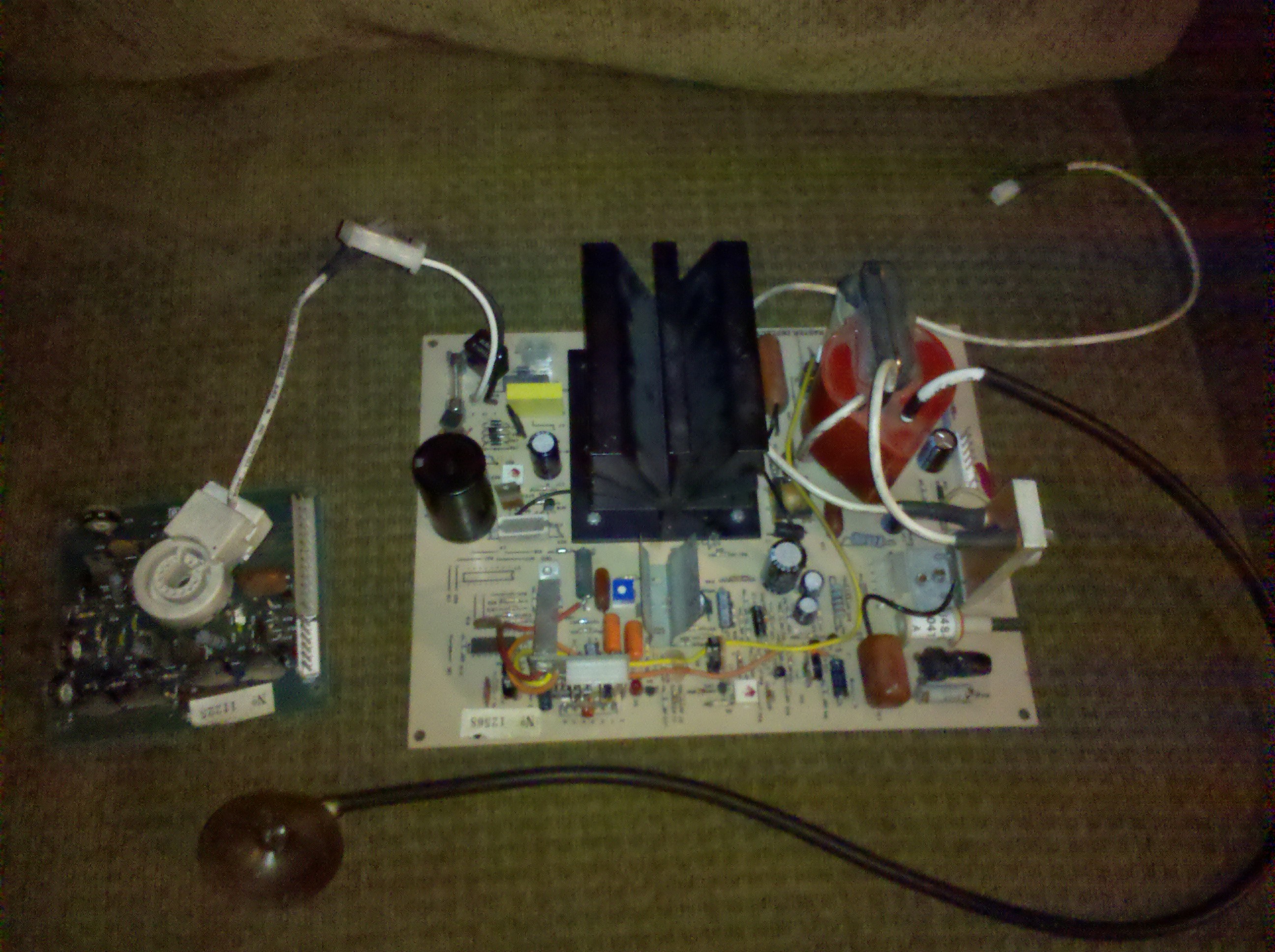
- The deflection PCB has a large black radial heatsink AND a bright RED flyback.
- The PCB's are not a part of a metal chassis frame
- They have good fiberglass PCB material like standard Atari stock (see pics below)
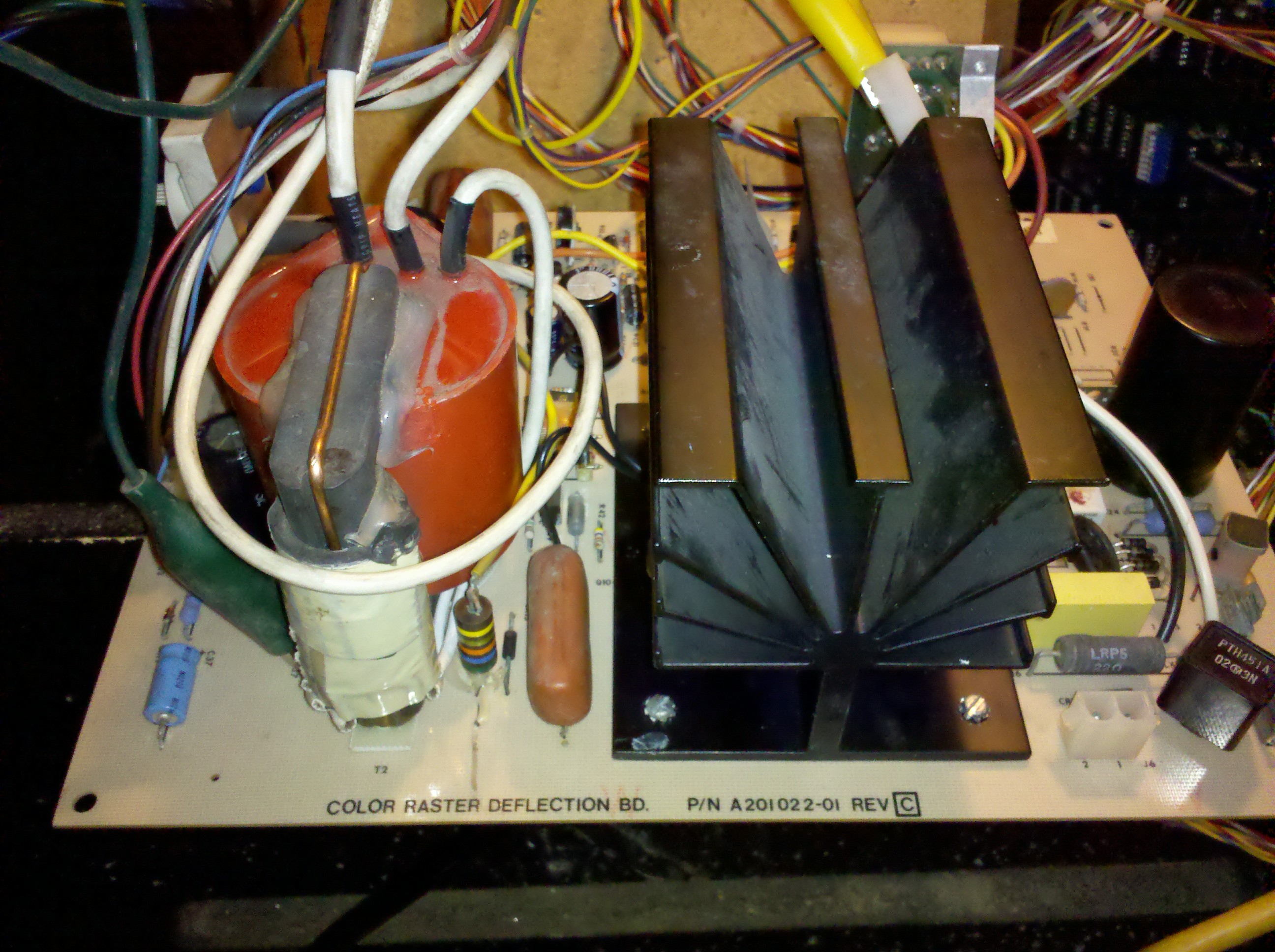
- They have Atari part numbers on them (ex A201022-01 see below)
- They are most likely non-working :-(
Deflection and Neck PCB's

|
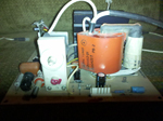
Deflection PCB #1
|
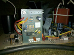
Deflection PCB #2
|
Deflection PLL PCB
|
History
Well the Atari/Amplifone Raster monitor probably has an elite place in the history of classic arcade games simply because
it was one part of a big problem Atari started to have in 1983/1984. Firstly, the reason I am naming this monitor the 'Atari/Amplifone'
is that it was manufactured by the Amplifone Corporation of Brownsville, TX which was a fully owned subsiderary of Atari.
Atari purchased Amplifone in order to manufacture their own monitors and other linear circuits in order to make higher
quality and lower cost parts for their games. Unfortunately for Atari, Amplifone did not succeed in making higher quality
parts. There are some excellent resources on Scott Evans' website (www.atarigames.com)
which detail many of the internal Atari meeting notes regarding Amplifone products.... The products amplifone was responsible
for with Atari were...
- Atari Switching Power Supply - this was supposedly used in 30 Crystal Castles games, all I,Robots and some Firefox's
- Amplifone Color Vector Monitor - used in some Gravitars, Quantum, Major Havoc and Star Wars
- Amplifone Raster Monitor - used in some Crystal Castles, some I,Robots and all Firefox's, plus all 3 monitors in TX-1's (can you say nightmare?)
- Laser Player Analog Board - used only in firefox obviously, but planned for Road Runner and Playland
Here are copies of the Amplifone Meeting notes from www.atarigames.com
- August 24th, 1982 Meeting Notes (.pdf 322KB)
- September 13th, 1982 Meeting Notes (.pdf 446KB)
- January 3rd, 1984 Meeting Notes (.pdf 471KB)
- January 12th, 1984 Meeting Notes (.pdf 227KB)
- January 17th, 1984 Meeting Notes (.pdf 228KB)
- January 24th, 1984 Meeting Notes (.pdf 229KB)
- January 31st, 1984 Meeting Notes (.pdf 258KB)
- February 21st, 1984 Meeting Notes (.pdf 338KB)
- March 2nd, 1984 Meeting Notes (.pdf 272KB)
- March 6th, 1984 Meeting Notes (.pdf 268KB)
- March 16th, 1984 Meeting Notes (.pdf 234KB)
Another great resource for Atari history has always been Jed Margolin (http://www.jmargolin.com/). Jed has
a HUGE amount of information on his site relating to many many Atari projects since he played a fairly major role at the company for so long.
Specifically, he has written up a nice history of Firefox where he mentions
some info about the design of both the Switching Power Supply and the Raster Monitor.
Technical Info
Major Parts
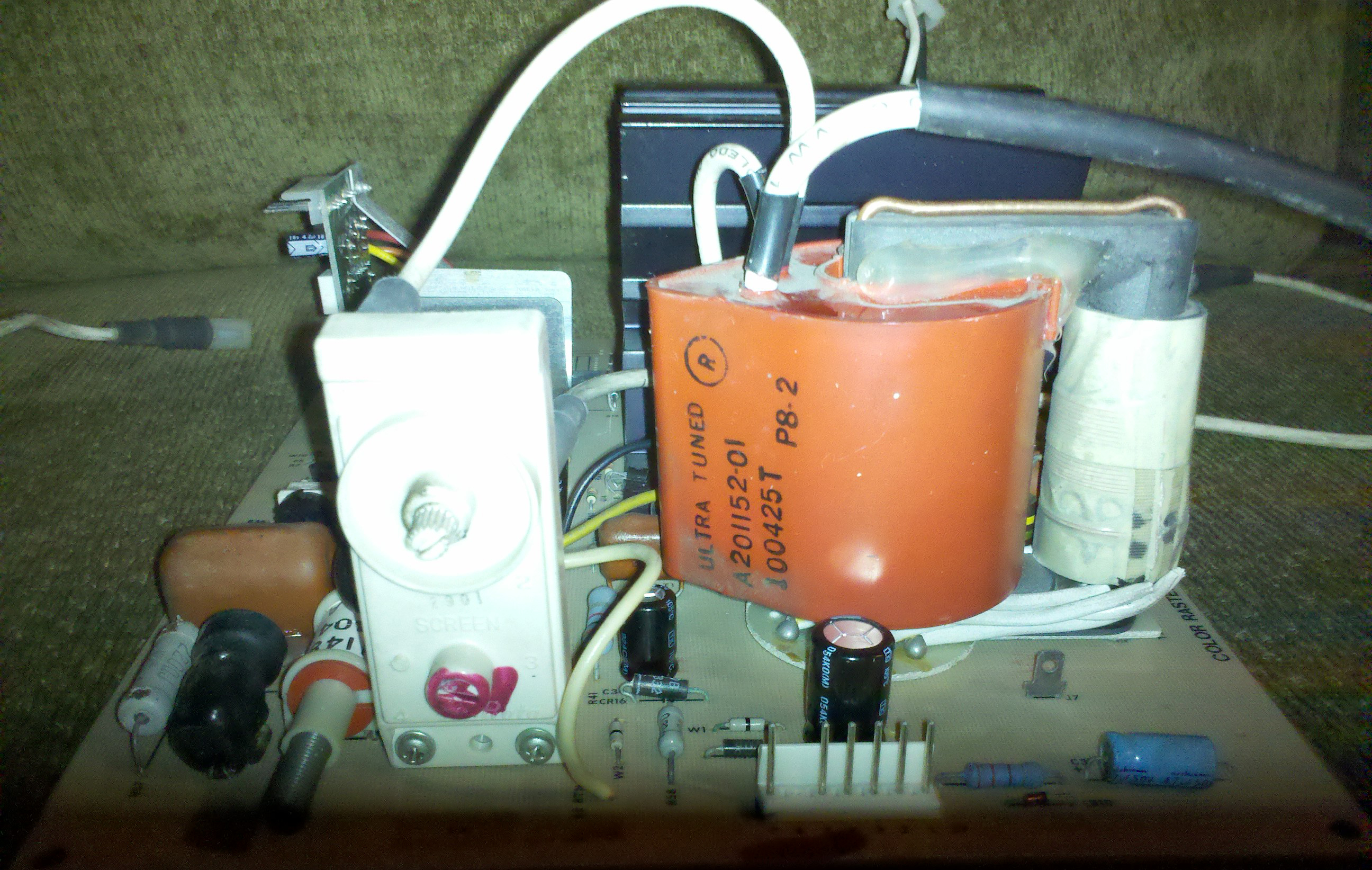
The Flyback Transformer
Let's dive into some specifics of the flyback transformer here, it seems that there are two or possibly three different part numbers for the flyback transformer
that were issued by Atari. The service manual lists A201144-01 as T2 Ultra-Tuned High-Voltage Transformer Assembly. However, the Raster Deflection PCB's that
I have contain transformers with A201152-01 stamped on them. Another number that came up is A201038-01 which is apparently the number stamped on an individual flyback
not mounted on a PCB, it may not be the correct transformer. If I can get one of each of these, I will attempt to figure out what the differences are.
The Flyback transformer is very similar to the HV transformer used in the Amplifone Vector monitor
- Is is bright red due to the plastic covering of the potted High Voltage windings and is labelled 'Ultra-Tuned'.
- The two core halves are held together by a 1/8" brass wire that allows the transformer to be dissasembled almost completely.
- The transformer operates with the core saturated for an internal 'self regulation' of the High Voltage output.
- Is is quite unreliable and is most likely not functional at this point.
That last bullet is probably the most important. Luckily for vectorheads, Mark Shostak has made replacement vector HV transformers which are properly manufactured and are reliable.
Unfortunately, if you have a raster monitor with a 'Dead RED' you are probably out of luck as there just isn't a demand for the raster flybacks to be remafactured. I am working on a hack
to use a Wells-Gardner K7000 series monitor flyback in place of the original but there are several issues I still need to overcome before I post the details here.
Deflection Coil
Part number and specifications for the two different deflection coils are as shown below:
| Model |
Part Number |
Horizontal Coil Resistance
(Red-Blue) |
Vertical Coil Resistance
(Brown-Yellow) |
| 19" Monitor |
A201050-01 |
1.9 Ohms |
10.8 Ohms |
| 25" Monitor |
A201138-01 |
? |
? |
Troubleshooting Notes
Here are some notes I am starting to put together about fixing these little beasties... Overall, the monitors seems to be fairly solid, there are definitely some issues that were fixed over time once they were
released into the wild with Firefox. However, the Persa Heel still seems to be the RED HV Transformer.
- By adding the PLL PCB on later versions, Amplifone was able to make sure that there was always a ~15.75KHz signal to the
horizontal oscillator circuit. According to notes by Jed Margolin, when the monitor didn't have a solid horizontal sync
signal from the game PCB it tended to have failures in the Horizontal Output section. By adding this little PCB, even if the game
PCB was unplugged all was OK. Once the game sync was connected the PLL (Phase Locked Loop) would simply match the game sync frequency.
I noticed that some pics online of Firefox cockpit's their deflection PCB's didn't have this little board. If you happen to have this situation
you might want to try and find one just to keep your game more reliable. The PLL PCB sits vertically on the deflection PCB and is held in place
by a metal bracket. See the pictures section for more clarity.
- The red HV Transformer (flyback in this case, the vector HV transformer was not a 'flyback') was certainly more standard as compared to the
Vector HV Transformer. Mostly, it had a 120V primary instead of a 24V primary (vector) which put much less strain on the Transformer. Unfortunately
the Raster HV transformer was also manufactured with the same materials and design philosophy as the Vector HV Transformer so it had the same
failure issues relating inductive mis-balances making it malfunction. My two HV Transformers are non-functional so Im looking for others if you happen to have one.
- The Amplifone Raster used a 19VJTP22 Tube. Technically, if you find any 19" tube that uses the BK-Precision Neck Pinout for a CR-23 adapter, it
should work. I went down to the local TV repair shop and got one for free. Keep the original purity rings and deflection yoke on the tube unless
you really need to pull the yoke for some reason. If you pull the purity rings, mark them with nail polish so you can put them back *exactly* the
way they were... it will save you some time. Also check out this article on salvaging tubes from TV's for more tips and information.
- Even tho the circuit board material is quite nice, the PCB traces are thin and easily damaged by desoldering equipment. Some components have very little
support and can crack their pads right off the board. I suggest folding leads over as much as possible out of a pad so you can solder it down to multiple places
if possible.
Repair
Overall, I would suggest getting things checked and working in the following order...
- 120V Regulator
- 5V Supply
- Horizontal Oscillator
- Horizontal Output
- Secondary Supplies
- Vertical Deflection
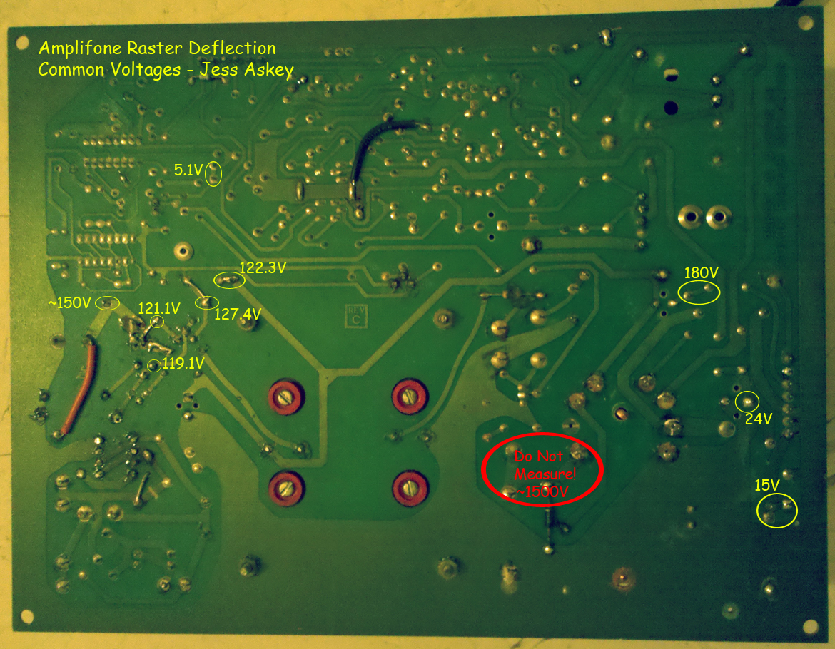
I made up a quick little voltage reference image that shows the common voltage measurements on
a working deflection PCB.
|
|
|
|
|
