Atari Pinball Repair/Maintenance Tip #1 |
Troubleshooting Atari Pinball Gas-discharge Displays
GAS-DISCHARGE DISPLAYS .....The displays are designed to be maintenance-free, so they normally require attention only if incorrect operation is observed. Use the following procedures to isolate and correct problems with the displays. Preliminary Operation Checks .....Make sure that the coin door is closed and locked. Then plug in the power cord and place the Power On/Off Switch in its on position. Immediately after AC power is applied, the Score Display should be showing all 8s and the PLAYER UP indications (1st up, 2nd, up, etc.) light one at a time, in numerical sequence. All 8's should be showing in the Credit Display and the Match/Ball Display.
Check on +90 and -90 Volts
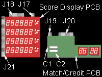
.....Remove the playfield glass, then remove the lower arch panel. Troubleshoot the displays as follows: WARNING: Use caution whenever AC voltage is applied to the game. High voltage is present on the bare terminals of the score panel's edge connector J21, and at various other points on both circuit boards. 1. Defeat the Interlock Safety Switch by pulling all the way out on the switch's spring-loaded plunger. 2. Place the Power On/Off Switch in the on position. 3. Connect a voltmeter across the following capacitors shown in the diagram, and check for the readings listed below: On the Match/Credit Display PCB place meter's ground lead on "plus" side of C2; other lead placed on "plus" side of C1 gives +90 volts reading, and on "minus" side of C2 gives -90 volts reading. On Score Panel PCB, place ground lead on "plus" side of C2; other lead on "plus" side of C1 gives +90 volts reading, and on "minus" side of C2 gives -90 volts reading. 4. If one or more readings are low (or at zero volts), check each PCB separately as follows. Disconnect J19 and re-measure the voltages on the Score Display PCB. If the voltages are OK, then some portion of the circuitry on the Match/Credit Display PCB is pulling down the supply voltages. If the voltages are still incorrect, reconnect J19, disconnect J17, and re-measure voltages on the Match/Credit display PCB. If voltages are OK, then some portion of the circuitry on the Score Display PCB is pulling down the supply voltages. If voltages remained incorrect while each board was checked separately, leave J17 and J19 both disconnected. Then check the +90 volt and -90 volt outputs on the Auxiliary PCB (where the high voltage power supply circuitry is located). These 90 volt supply voltages must both be present on each display PCB before the displays can light up. .....If all voltage readings on the display PCBs are within 5% of the correct values, then go on to the next portion of the procedure. Score Panel Removal and Visual Checks .....After the +90 volt and -90 volt supply voltages have been verified, the next troubleshooting step on the score panel will be to remove it from connector J21. 1. Turn off AC power to the game, preferably by pulling out the power plug from the wall outlet. 2. Remove the metal clips holding the score panel onto the bracket arms of J21. 3. Using your right hand, grasp the right edge of the score panel. Carefully lift it up approximately 1/4-inch, and then pull it straight out and remove it completely. 4. Examine the positions of the terminal pins on J21. Tips of the pins should be aligned in the same plane, and not be bent down or up. If not bent out of alignment, all pins can then make contact with the score panel's terminal strips when the panel is plugged in. 5. Next examine the condition of the terminal strips on the score panel. If the surfaces of the strips are corroded, use a pencil eraser to clean them off. Be careful, however not to rub the eraser against any of the tiny metal ribbons touching certain strips up near the glass "seal". These ribbons must be perfectly centered over the correct pins, not halfway off. Replacement of Score Panel .....After the visual checks have been made on the J21 terminal pins and on the score panel, the original score panel can be put back, or else a new score panel can be substituted in its place. Carefully observe the following procedure when replacing the score panel. 1. Using both hands, grasp the right-hand edge of the panel and carefully slide it fully into connector J21, perfectly aligned. Then lower the edge down until the entire panel rests in the bracket arms. You will note some free space on each side between the panel and the brackets. At the factory a rubbery substance called RTV was placed between the bracket arms and the score panel. This substance provides a cushion between the glass panel and the metal arms, and positions the panel so that connector J21's terminal pins line up exactly with the panel's terminal strips. Be sure that they are aligned correctly.
BACK to the Atari Pinball website Copyright © 1998-2001 by Travis Haagen. All Rights Reserved. |

